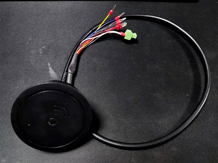
Barrier radar smart sensor
Product description
1. Product specifications
1.1 Appearance material: black ABS material
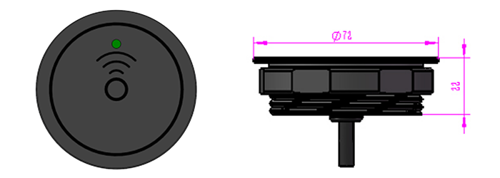
1.2 Dimensions: 72mm (length) 72mm (width) 22mm (height)
2. Product parameter table

Attachment 1: Microwave Detector Specifications and Dimensions

4. Interface definition


5. Equipment installation
5.1 Installation specifications
The installation height of the microwave detector with the barrier gate is 550mm-750mm from the ground, and the distance between the microwave detector and the barrier barrier (the closer the gate lever is, the better) the indicator light is upward.

6. Microwave detector debugging
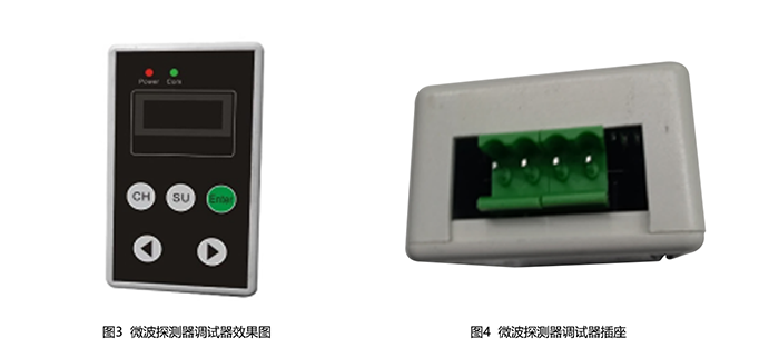
6.1 Appearance of Microwave Detector

6.2 Microwave detector debugger preparation
Connect the microwave detector to the 12V DC power supply, and then connect the microwave detector debugging plug to the microwave detector debugging socket to complete the preparation work;
Note: Check the microwave detector and make sure the microwave detector is powered on (the debugger cannot be plugged in if it is not powered on)
6.3 Microwave detector debugger function control

7. Instructions for use
7.1 Please strictly follow the indications in the chart in the product manual, and use it normally within the corresponding input voltage, output voltage, current and other parameters. When the maximum value is exceeded, the reliability of the product will be reduced and the circuit will be permanently damaged. , resulting in product failure.
7.2 In order to avoid damage to the circuit, it should be handled with care. ESD electrostatic protection measures should be taken in all stages of storage, handling, assembly and testing.
7.3 Before the product leaves the factory, the antenna transmission frequency has been calibrated and adjusted, and no further adjustment is required.
8. Shell installation method and material selection
When installing, the sensor housing cannot use metal materials or metal layers, and non-carbon-containing plastic materials or plastic foam can be used.
Correct way:
1. When the shell is made of plastic materials (ABS, PVC, etc.), the thickness and space of the shell must be correctly estimated, and the antenna should be wrapped in a way that does not directly contact the radar antenna structure.
2. When the shell is made of foam material (such as Stypopor or similar material), the relative dielectric constant of the material should be close to 1.
Wrong method:
One, wrap the antenna with metal foil or some metal parts.
2, Spray the antenna structure surface with any kind of paint.
3, Wrap the antenna with CFK sheet (conductive).
4. The plastic material is in direct contact with the corroded antenna structure (it has a high dielectric constant effect on the resonant frequency of the patch).
Shell recommended size:
For 24GHz radar, according to experience, the shell can be made of plastic material with a thickness of about 3mm, and keep a distance of 36mm from the surface of the radar antenna.
If a thicker plastic material is used, the increase in insertion loss must be considered; at the same time, an over-thick casing may affect the antenna direction angle and sensing distance.
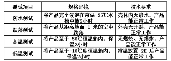
9. Environmental adaptability

10.safety performance

11. Other tests

Send Inquiry
